This post was written as a project proposal for an electronics course, the project was not completed.
Last year I participated in the Midwest High-Power Rocket Competition on the UW-River Falls team, wherein we were tasked with the building and launching of a high power rocket on which there was a mechanism to control the apogee via air braking. The flight computer on said rocket was less than satisfactory, a result of compromises for power and weight as well as a lack of proper communication on the programming end. At the time, I had very little experience with electronics and therefore strictly worked on the programming end which was later rewritten by other members of the team. With this project, I aim to rebuild this computer from scratch with the knowledge and experience I have gained both in and out of classes since the competition.
First, I need to define the functionality of the computer and the meaning of success for this project. The circuitry will consist first of sensors to collect data about the rocket’s current condition: pressure, acceleration, and rotation; this data will then be processed by a microcontroller to find another set of parameters: altitude, velocity, and tilt. All of these parameters should be stored to some accessible disc, this will likely be handled by an SD card in this case. Finally, the microcontroller will control certain aspects of the rocket in order to adjust the rocket into a desired position. In the original competition, this was done by rotating a motor which would extend fins horizontally to slow the rocket. However, due to difficulty in testing whether such a mechanism is performing correctly, I am opting for a set of rotating fins that will correct a rocket’s rotation to keep its trajectory normal to the ground. As such, the success of this project will be to create a board that can be mounted in a rocket, store the aforementioned data, and rotate a set of fins in a manner that would correct the trajectory of said rocket.
The parts I currently have planned (while I have done quite a bit of research on these parts, it is possible that some do not perform to expectation and may need to be replaces) are as follows:
| Name | Qty | Price | Total |
|---|---|---|---|
| ATmega328P-PU | 1 | 1.98 | 1.98 |
| Adafruit 254 | 1 | 7.50 | 7.50 |
| 10 DOF IMU Sensor (B) | 1 | 18.99 | 18.99 |
| CP2102 | 1 | 3.98 | 3.98 |
| SG90 9G Mini Servo | 2 | 3.29 | 6.58 |
| PS1240 Piezo Buzzer | 1 | 1.50 | 1.50 |
| 90020 20pF Capacitor | 2 | 0.90 | 1.80 |
| ATS160-E | 1 | 0.36 | 0.36 |
| C315C104M5U5TA | 1 | 0.30 | 0.30 |
| 100 Ohm Resistor | 1 | ~0.04 | ~0.04 |
I’ve opted for the 10 DOF IMU rather than a separate accelerometer, gyroscope, and barometer as it reduces the complexity of the system as well as the number of I2C channels needed. This current configuration will consist of a main board with three breakout boards for USB, microSD, and IMU. As an alternative, this entire circuit could be miniaturized by rebuilding all of the breakouts on a single PCB with surface mounting (since a lot of the ICs are only available as such). However, this option can really only be pursued as an extension to the current project as it would require purchasing many new parts and printing a PCB, which should only be done after a decent proof of concept. Given that, here is the currently planned configuration as a schematic:
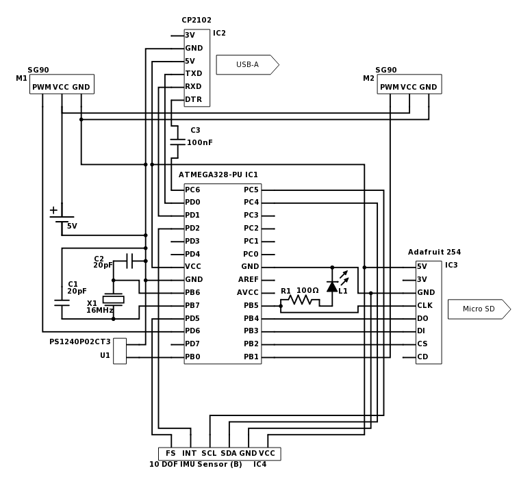
For initial testing purposes, the center area with the ATmega328 (IC1), crystal (X1, C1, C2), and LED (L1) can all be replaced with an Arduino Uno until said portion is proven to be in working order. Not currently listed in the above parts list is a breadboard, either solderless for initial prototyping or otherwise for a bit more permanent construction, as well as some form of mounting which may be either attached to a ring of blue tube or a plastic mount time depending.
References
http://www.atmel.com/Images/Atmel-42735-8-bit-AVR-Microcontroller-ATmega328-328P_datasheet.pdf
https://www.arduino.cc/en/Hacking/PinMapping168
https://learn.adafruit.com/adafruit-micro-sd-breakout-board-card-tutorial/wiring
http://www.waveshare.com/10-DOF-IMU-Sensor-B.htm
http://tronixstuff.com/2010/10/20/tutorial-arduino-and-the-i2c-bus/
https://www.arduino.cc/en/Reference/Wire
https://learn.sparkfun.com/tutorials/minigen-hookup-guide/arduino-library (main point from this one is the part about the pin number, which I have on 5 in the schematic)
http://www.ecfr.gov/cgi-bin/text-idx?SID=86008bdffd1fb2e79cc5df41a180750a&node=22:1.0.1.13.58&rgn=div5#sg22.1.121.sg (better safe than sorry)
https://product.tdk.com/info/en/catalog/datasheets/ef532_ps.pdf