This post was written as a project proposal but never submitted for funding.
Introduction
The acousto-optical effect is the change in refractive index of a material caused by an acoustic wave applied to said material. This is a particular case of photoelasticity, which can be used to experimentally measure stress distributions within a material1, where the difference in refractive indices (represented by the optic indicatrix2 $B$) along each axis is caused by acoustic waves rather than mechanical tension. The change in optical indicatrices is found then with the equation
\[\nabla B_i=p_{ij}a{j},\tag1\]where $p_{ij}$ is the photoelastic tensor and $a_j$ is the strain3. However, it can be assumed that if a laser is being used as a light source normal to a single axis $z$, then only the refractive index along said axis needs to be calculated to predict the path of the light. It is also assumed that the acoustic wave applied to the refractive material is planar in the following calculation of the refractive index:
\[n(z,t)=n_0+\Delta n\cos(2\pi ft-Kz),\tag2\]where $n_0$ is refractive index of the material without strain, $f$ is the frequency and $K$ is the wave number of the acoustic wave, and $\Delta n$ is the refractive index change caused by the acoustic wave:
\[\Delta n=-\frac{1}{2}n_0^3 pa.\tag3\]This creates a diffraction grating along the z-axis moving as the acoustic wave moves along the same axis. The diffraction pattern of this grating will fall into one of two categories: the Raman-Nath Regime or the Bragg Regime, determined by the Klein-Cook Parameter:
\[Q=\frac{2\pi\lambda_0L}{n_0\Lambda^2} =\frac{2\pi\lambda_0Lf^2}{n_0v^2},\tag4\]where $\lambda_0$ is the wavelength of the optic wave; $L$ is the distance across the acoustic wave that the optic wave travels; $\Lambda$ is the wavelength, $f$ is the frequency, and $v$ is the velocity of the acoustic wave. The diffraction falls into the Raman-Nath Regime when $Q\ll 1$, and the Bragg Regime when $Q\gg 1$. The Raman-Nath Regime gives multiple diffractions at several angles, which is not optimal for the creation of a deflector, as such it is best to remain within the Bragg Regime.
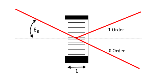
FIGURE 1. An example of an acousto-optic deflector, showing the material with the acoustic waves vertically oriented and a width of $L$. This example assumes Bragg Regime, and therefore has an incident angle of $\theta_B$ from the horizontal, and a diffraction pattern with two maxima: the 0th order maximum at $-\theta_B$ and the 1st order maximum at $\theta_B$ from the horizontal.
To ensure that the deflector follows this condition, the Klein-Cook Parameter can be substituted into the condition for the Bragg Regime:
\[\begin{align} \frac{2\pi\lambda_0L}{n_0\Lambda^2}&\gg1,\tag{5a}\\ 2\pi\lambda_0L&\gg n_0\Lambda^2,\tag{5b} \end{align}\]which can be further simplified based on a few assumptions: using a common red HeNe laser4 as the light source such that $\lambda_0 = 632.8nm$, and paratellurite (TeO2)5 as the material through which the acoustic waves are produced such that6 $n_0 = 2.259$. Substituting these values, the equation becomes:
\[L\gg\frac{b}{2\pi}\Lambda^2,\tag6\]where $b = 3.570\cdot10^6 m^{-1}$.
Under the previous assumptions, and in the Bragg Regime, the diffracted light beams will be found around the Bragg angle $\theta_B$ is given by the function:
\[\sin(\theta_B)=-\frac{\lambda_0f}{2n_iv} \left[ 1+\frac{v^2}{\lambda_0^2f^2}(n_i^2-n_0^2)\right],\tag7\]where $n_i$ is the refractive index of the incident beam. If $n_i=n_0$, as it would in an isotropic material (a crystal whose refractive index is equal in all directions), then the above equation simplifies nicely to:
\[\sin(\theta_B)=-\frac{\lambda_0f}{2n_iv},\tag8\]Paratellerium is not isotropic, it is uniaxial, having the same refractive index along two axes but a difference in the third axis, giving its optical indicatrix the shape of a uniaxial ellipsoidal surface. However, so long as the material is oriented in such a way that the angle of incidence is between the two axes of equal refractive index, the $n_i=n_0$ for this case and Eq. 8 can be used rather than the more complicated Eq. 7.
The clearest usage of an acousto-optical deflector is to create a scanning beam, changing the 1st order diffraction’s angle by adjusting the acoustic wavelength. This would suggest that a function for $\theta_B$ with respect to $\Lambda$ would be a more beneficial form:
\[\theta_B=\arcsin\left(-\frac{1}{2b\Lambda}\right).\tag9\]Methodology
To build the deflector for a wavelength of $632.8nm$, a laser of said frequency is necessary in order to assure proper construction and tuning.
The deflector itself requires a tellurium dioxide crystal, as that is material around which the calculations were done in the previous section; the size of the crystal should be small enough to make the entire device wieldy but not too small as to require extremely high frequency (low wavelength) acoustic waves to produce the desired acousto-optic effect. As such a 10x9x5mm7 crystal should sufficiently meet these requirements, updating the Klein-Cook parameter in Eq. 6 to:
\[\begin{align} \frac{0.005\cdot2\pi}{3.570\cdot10^6}m^2&\gg\Lambda^2,\tag{10a}\\ \Lambda^2&\ll8.800\cdot10^{-9}m^2,\tag{10b}\\ \Lambda&\ll9.380\cdot10^{-5}m,\tag{10c} \end{align}\]which can then be used to find a range of frequencies for the acoustic waves needed to properly produce this effect. Given that the velocity of sound in paratellurium is $4260m/s$:
\[\begin{align} f&=\frac{v}\Lambda,\tag{11a}\\ f&\gg\frac{4260m/s}{9.380\cdot10^{-5}m},\tag{11b}\\ f&\gg 4.542\cdot10^7Hz,\tag{11c} \end{align}\]as such a piezeo-electric transducer capable of producing acoustic waves with a frequency on the order of 10 MHz would be necessary. The dimensions of this transducer should also match the dimensions of the crystal, such that the transducer covers an area of at least 5x5mm on the bottom of the paratellurite. To prevent the acoustic waves within the crystal from reflecting of causing interference that may cause diffraction that deviates from the desired effect, some acoustic absorbing material of at least the same size as the transducer (5x5mm) needs to be placed on the opposing side of the crystal.
Housing for the deflector could easily be made a variety of ways, given that the casing would be relatively simple yet small. Perhaps one of the more precise methods would be to 3D print the casing. If such a printer is available for use on this project, then the only further requirement to pursue this method would be to obtain the ABS plastic for the construction. Other methods, such as woodworking or cutting metal sheeting, present their own problems: wood has a tendency to burn when heated, while the laser in this case may not have as much of a problem with this, it is best to avoid this situation as much as possible; metal is often very reflective, which could easily cause an incident with a laser, though sufficient coating may prevent this, again it is best to avoid.
-
H. Tanping, Y. Xiuying, Y. Dongmei, X. Hongji, 2010 Int’l Conf. Comp., Mechatronics, Electrical Engineering, 156 (2010). ↩︎
-
http://wwwf.imperial.ac.uk/ (2013). ↩︎
-
http://mt-berlin.com/ (Unpublished). ↩︎
-
Using a HeNe laser as the light source since it is the only laser with which I have experience. It is also worth noting that having a source with a predetermined polarization allows for a more complete understanding of the acousto-optic effect via experimentation, and the HeNe lasers kept in the UW-River Falls Phys. Dept. exhibit such properties. ↩︎
-
J. Appl. Phys. 43, 4489 (1972) ↩︎
-
Calculated using http://acoustooptics.phys.msu.su/dispersion.asp for paratellerium with an optic wavelength of 0.6328mkm. ↩︎
-
This size is based on the crystals available at http://www.unitedcrystals.com/TeO2.html. ↩︎